As you know, Arduino is a platform for simplicity, making the realization of ideas a lot easier, but also because we will not be able to fully exploit the power of micro. The controller is located on the Arduino board. What I feel most sorry for is the lack of interrupt vector in the Arduino environment (Arduino currently only has built-in function that supports external interrupts) .
In this article, I will show you how to use the Timer / Counter on the Arduino and some interruptions of these Timers / Counter.
1. Preparation
-
1x Arduino board (I used Arduino UNO R3 with ATmega328p chip ).
- Some LEDs and resistors 220 → 560 Ohm.
- ATmega328p Datasheet.
2. Introduction
On the Arduino chip Atmega328p 3 Timer / Counter is: Timer / Counter0 (8bit), Timer / Counter1 (16 bit), Timer / Counter2 (8 bits).
In order not to affect the delay () and millis () functions of the Arduino, I will not mention Timer / Counter0.
As I've introduced, Timer / Count functions as: Counting events, Timing and PWM pulses, to keep things simple, I just introduced the basic function of Timer / Counter when programming on Arduino is " Arduino has built-in analogWrite built-in function to generate PWM pulse, so we will not mention it anymore.)
- Timer / Counter1 is a 16 bit multi-timer / counter, consisting of 5 active modes.
- Timer / Counter2: is a set of Timer / Counter 8 bit, including 4 modes.
In the article I will introduce Normal Mode and Clear Timer on Compare Match (CTC) mode on Timer / Counter1 and Timer / Counter2.
Well, for convenience, I will abbreviate Timer / Counter to T / C.
Before we start, there are some important definitions we need to know:
-
BOTTOM : is the lowest value that 1 T / C achieved, of course BOTTOM is always 0.
-
MAX : is the maximum value that a T / C can achieve, in the 8 bit register value MAX = 2 ^ 8 -1 = 255, in the 16 bit register value MAX = 2 ^ 16 - 1 = 65535 And of course the MAX value is also fixed with each T / C.
-
TOP : is the peak value at which the T / C changes state, the TOP value is not necessarily equal to the MAX that can be changed by the registers. We will find out later.
-
Interrupt : (also known as Interrupt) is a program with the highest priority, which is executed immediately when there is an interrupt signal. To understand more, you ask google nhé!
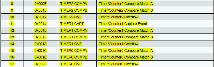
Table 1: Interrupt Vectors of Timer / Counter on ATmega328
3. Timer / Counter 1
3.1 Introduction to registers
3.1.1 TCNT1 register (Timer / Counter 1 Register)
A 16-bit register that stores the value of Timer / Counter1, which allows direct reading and writing, so that we can perform assignments or change the value of TCNT1 .
3.1.2 TCCR1B register (Timer / Counter 1 Control Register B)
It is one of the two active control circuits of Timer / Counter1 (along with TCCR1A , but for simple purposes we only need the TCCR1B register ).
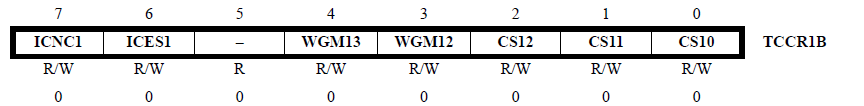
Table 2: TCCR1B register
In the TCCR1B register we only need to use 3 bits CS10 , CS11 , CS12 to select the clock for T / C1. We will refer to this table:
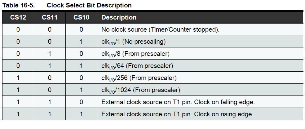
Table 3: Description of the Clock Select Bit on the TCCR1B register
By default, the Atmega328p chip on the Arduino runs at 16MHz, prescaler = 64. This means: By default, the Arduino T / Cs will have an operating frequency of 16MHz / 64 = 250kHz.
3.1.3 Timer / Counter1 Interrupt Mask Register
The register that holds the Interrupt Mask of T / C1. This is the register that helps us implement the Timer Interrupt. On the TIMSK1 register note the following bits:
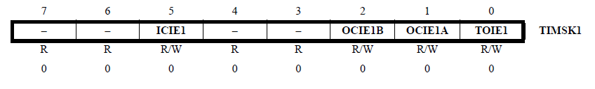
Table 4: TIMSK1 register (Timer / Counter1)
-
Bit 5 - ICIE1 : Input Capture Interrupt Enable - Allows interrupts when using Input Capture.
-
Bit 2 - OCIE1B : Output Compare Interrupt Enable 1 channel B - Enable interrupts when using Output Compare in channel B.
-
Bit 1 - OCIE1A : Output Compare Interrupt Enable 1 channel A - Enable interrupts when using Output Compare in channel A.
-
Bit 0 - TOIE1 : Overflow Interrupt Enable 1 - Enable interrupt when overflow occurs on T / C.
(You keep calm, things like Output Compare, Input Capture, Overflow I will introduce below).
3.1.4 OCR1A and OCR1B (Output Compare Register channel A and channel B)
Store comparable values at channel A and channel B: when T / C1 is active, TCNT1 value is incremented, this value is continuously compared with values in OCR1A and OCR1B registers, this comparison The "Output Compare", when the value of TCNT1 is equal to the value of OCR1A (or OCR1B), then "Match" occurs, there will be an interrupt performed (if enabled in TIMSK1 register).
3.1.5 Input Capture Register 1 ( ICR1 )
The ICR1 register value will be updated with the TCNT1 register each time an event occurs on the ICP1 footprint (corresponding to the digital 8th leg of the Arduino). This function I will introduce in another article.
3.2 Modes of Timer / Counter 1
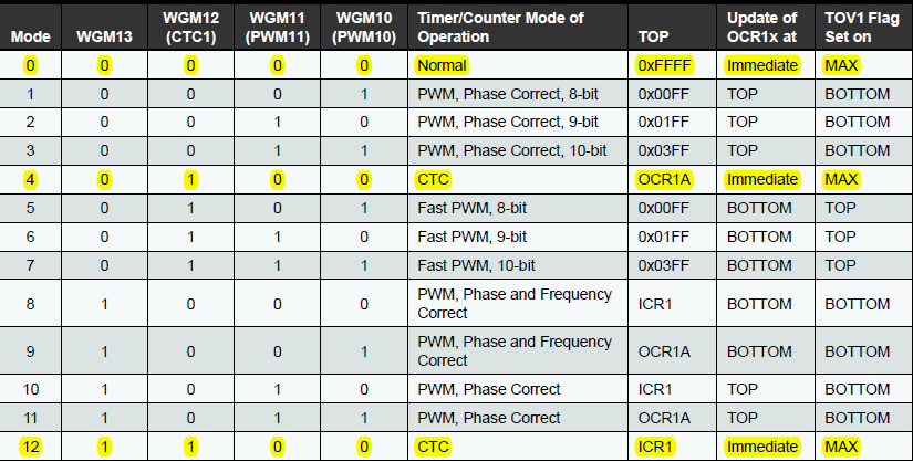
Table 5: Waveform Generation Mode Bit (Timer / Counter1)
I will introduce 2 most basic modes of T / C1: Normal Mode and CTC Mode .
3.2.1 Normal Mode
This is the simplest operation mode of T / C1 (mode 0), the value of TCNT1 register will increase from 0 (BOTTOM) to 65535 (MAX) and return to 0. If we assign a TCNT1 Anyhow, TCNT1 will start counting from this value.
Example: You want to write a program that reads data from the heat sensor every 0.1s, but there are some delay functions in the program body, so you will not guarantee that you can update the temperature value each time. 0.1s using only if and millis () functions. The alternative here is that we will use Timer / Counter Interrupt.
By default, the Atmega328p chip on the Arduino runs at 16MHz, prescaler = 64, so the time to TCNT1 goes up to 1 unit is 64 / 16MHz = 4us, the time to T / C1 counts from 0 to 65535 is 4us * 65536 = 0.262144s, the time we need to create is 0.1s (since 0.1 <0.262144), so we need 0.1s / 4us = 25000 counts. The initial value of TCNT1 = 65536 - 25000 = 40536.
3.2.1.1 Programming
-
#include <avr / interrupt.h>
-
#define sensor A0
-
-
Volatile int temp ;
-
-
Void setup ()
- {{
-
Serial . Begin ( 9600 );
-
Cli (); // turn off the global interrupt
-
-
/ * Reset Timer / Counter1 * /
-
TCCR1A = 0 ;
-
TCCR1B = 0 ;
-
TIMSK1 = 0 ;
-
-
/ * Setup Timer / Counter1 * /
-
TCCR1B | = ( 1 << CS11 ) | ( 1 << CS10 ); // prescale = 64
-
TCNT1 = 40536 ;
-
TIMSK1 = ( 1 << TOIE1 ); // Overflow interrupt enable
-
Sei (); // allow global interrupt
- }
-
-
Void loop ()
- {{
-
/ * Add main program code here * /
- }
-
-
-
ISR ( TIMER1_OVF_vect )
- {{
-
TCNT1 = 40536 ;
-
Temp = analogRead ( sensor );
-
Serial . Print ( F ( "Temp:" ));
-
Serial . Println ( temp );
- }
3.2.1.2 Explanation
- #include <avr / interrupt.h> is the AVR's Interrupt Library.
- The temp variable must be declared volatile since it is used both in the main program and in the interrupt program.
- Cli () is used to turn off global interrupts.
- Refer to the Waveform Generation Mode Bit table, we find that to set T / C1 in mode 0, the bits should be set as follows: WGM13 = 0, WGM12 = 0, WGM11 = 0, WGM10 = 0, This bit is 0 so we do not need to care about it in the TCCR1B register anymore.
- TCCR1B | = (1 << CS11) | (1 << CS10) is used to set prescaler = 64. (Refer to the Clock Select Bit table.)
- Sei () is used to enable global interrupts.
- Expressions like (1 << CS11) are used to set CS11 bit to 1.
-
ISR ( Vector_name ) is the interrupt server, where ISR is the keyword, Vector_name in this program is TIMER1_OVF_vect , which means "Overflow on Timer / Counter1".
- In the interrupt service, we need to assign the initial value to TCNT1 = 40536 because T / C1 now counts over 65535 and returns 0. If we do not assign TCNT1 = 40536 we will not create 0.1s as desired.
3.2.2 Clear Timer on Compare Match (CTC) mode
There are 2 CTC modes on T / C1 mode 4 and mode 12
I will introduce mode 4 first. To select mode 4, we need to set the following bits: WGM13 = 0, WGM12 = 1, WGM11 = 0, WGM10 = 0.
The CTC mode works as follows: The OCR1A register holds the TOP value, the TCNT1 register starts counting from 0, when the TCNT1 = OCR1A value is "Compare Match", then the Match Match interrupt can occur if the OCIE1A bit has been set. Set in the TIMSK1 register.
You note that only the OCR1A register is used to store the COMPARE value in CTC mode only!
Back to normal mode, I will do with CTC Mode as follows:
3.2.2.1 Programming
-
#include <avr / interrupt.h>
-
#define sensor A0
-
-
Volatile int temp ;
-
-
Void setup ()
- {{
-
Serial . Begin ( 9600 );
-
Cli (); // turn off the global interrupt
-
-
/ * Reset Timer / Counter1 * /
-
TCCR1A = 0 ;
-
TCCR1B = 0 ;
-
TIMSK1 = 0 ;
-
-
/ * Setup Timer / Counter1 * /
-
TCCR1B | = ( 1 << WGM12 ) | ( 1 << CS11 ) | ( 1 << CS10 ); // prescale = 64 and CTC mode 4
-
OCR1A = 24999 ; // initialize OCR1A
-
TIMSK1 = ( 1 << OCIE1A ); // Output Compare Interrupt Enable Timer / Counter1 channel A
-
Sei (); // allow global interrupt
- }
-
-
Void loop ()
- {{
-
/ * Add main program code here * /
- }
-
-
-
ISR ( TIMER1_COMPA_vect )
- {{
-
Temp = analogRead ( sensor );
-
Serial . Print ( F ( "Temp:" ));
-
Serial . Println ( temp );
- }
3.2.2.2 Explanations
- To select mode 4, in the settings for the TCCR1B register we need to set the WGM12 bit to 1, ie (1 << WMG12).
- To generate 0.1s (at 16MHz, prescaler = 64) we need T / C1 to count 25000 times, so TOP value = OCR1A = 24999.
- To enable the Match Match Counter Timer / Counter 1 channel A, we need to set the OCIE1A bit of the TIMSK1 register to 1.
- At the interrupt function, we change to ISR (TIMER1_COMPA_vect) to match Match Match Interrupt T / C1. (You refer to the table above Interrupt Vectors).
To use Mode 12, we just need to change a bit like this:
- // prescale = 64 and CTC mode 12
-
TCCR1B | = ( 1 << WGM12 ) | ( 1 << WGM13 ) | ( 1 << CS11 ) | ( 1 << CS10 );
-
- // initialize ICR1
-
ICR1 = 24999 ;
-
- // Input Capture Interrupt Enable Timer / Counter1 channel A
-
TIMSK1 = ( 1 << ICIE1 );
-
- // Input Capture Interrupt Vector
-
ISR ( TIMER1_CAPT_vect ) {...}
3.2.2.3 Apply CTC mode to simplify external event counting
Example: I will use the PIR motion sensor HC-SR501 to count the number of people entering the room, every 10 people in the LED will flash once. (Of course, this is just an example of CTC mode, I'm not sure how effective it is).
We will connect the OUT pins of the sensor to Arduino's digital 5 (T1 pin ATmega328).
Program
-
#include <avr / interrupt.h>
-
#define LED 10
-
-
Void setup ()
- {{
-
PinMode ( LED , OUTPUT );
-
Cli ();
-
TCCR1A = 0 ;
-
TCCR1B = 0 ;
-
TIMSK1 = 0 ;
-
-
/ * CTC mode 4, External Clock source from T1 pin, clock on falling edge. * /
-
TCCR1B | = ( 1 << WGM12 ) | ( 1 << CS12 ) | ( 1 << CS11 );
-
OCR1A = 9 ;
-
TIMSK1 | = ( 1 << OCIE1A );
-
Sei ();
- }
-
-
Void loop ()
- {{
-
// nothing here
- }
-
-
ISR ( TIMER1_COMPA_vect )
- {{
-
DigitalWrite ( LED , 1 );
-
Delay ( 200 );
-
DigitalWrite ( LED , 0 );
- }
Explain
Whenever motion is detected, the sensor will return the HIGH of the OUT pin, so we will get this signal as the source clock for the T / C1 by setting the CS12 and CS11 bits of the TCCR1B register to 1:
-
TCCR1B | = ( 1 << WGM12 ) | ( 1 << CS12 ) | ( 1 << CS11 );
At the request of example, for every 10 people passing through the sensor, the LED flashes once, so the COMPARE value in the OCR1A register = 9.
The rest of the code is similar to the first example, you refer back to the Waveform Generation Mode Bit (Timer / Counter1) and Clock select bits to better understand how to set the registers!
4. Timer / Counter 2
4.1 Registers
On T / C2 there are similar registers T / C1
4.1.1 TCNT2 register (Timer / Counter 2 Register)
It is an 8 bit register that holds the value of Timer / Counter2.
4.1.2 TCCR2A and TCCR2B (Timer / Counter 2 Control Register A and B)
These are two controllers that control the operation of Timer / Counter2.
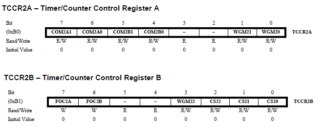
Table 6: TCCR2A and TCCR2B (Timer / Counter 2)
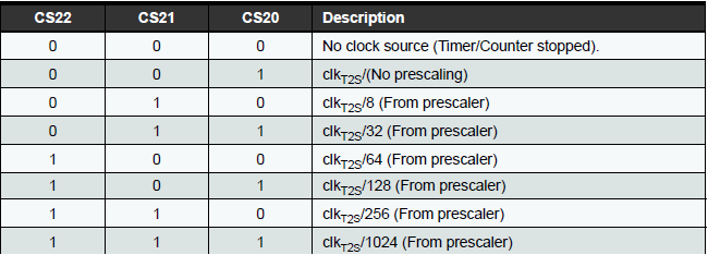
Table 7: Description of the Clock Select Bit
 4.1.3 TIMSK2 register (Timer / Counter2 Interrupt Mask Register)
The register that holds the interrupt mask of T / C2.
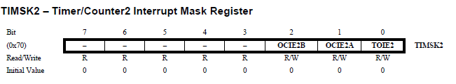
Table 8: TIMSK2 register (Timer / Counter 2)
4.1.4 OCR2A and OCR2B (Output Compare Register channel A and channel B)
Store comparable values at channel A and channel B when T / C2 operates.
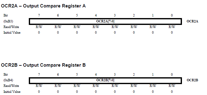
Table 9: Storage of comparable values in channel A and channel B when T / C2 operates.
4.2 Operating modes
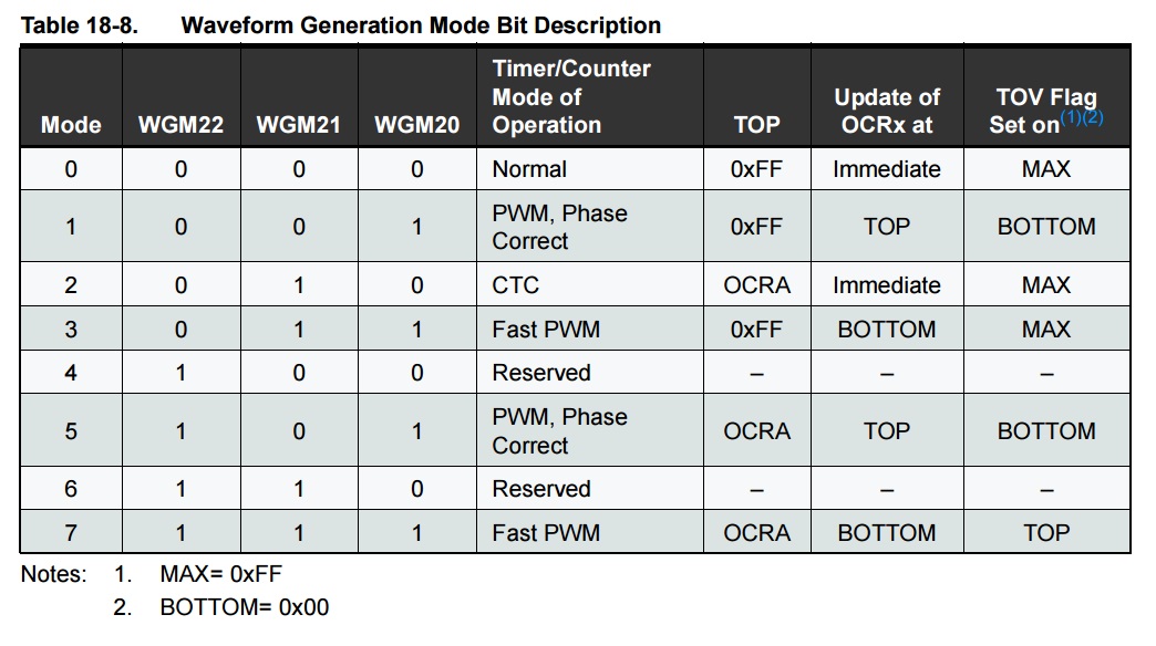
According to Waveform Generation Mode bit, T / C2 has Normal Mode 0 and CTC mode 2 .
To avoid duplicate content with T / C1, I only introduce how to set register in T / C2.
-
In Normal Mode , you only need to set the CS20, CS21, CS22 bits in the TCCR2B register to select the prescaler.
-
In CTC Mode : besides set the bits in the TCCR2B register to select the prescaler, you need to set the WGM21 bit to 1 by the line: TCCR2A | = (1 << WGM21);
- How to set TIMSK2 register is similar to TIMSK1: OCIE2A (Output Compare Interrupt Enable 2 Channel A), OCIE2B, TOIE2 (Timer Overflow Interrupt 2 Enable).
5. Conclusion
Hope this article will help you to program Arduino more efficiently. In the article may be a mistake, you just glazed when asking questions nhé!
I wish you success and happy Arduino!
6. Reference
Unit 4 - Timer - Counter: http://www.hocavr.com/index.php/en/lectures/timer-counter
